
Inspect and test a passive extension lead with a PrimeTest 250+
Formally inspect and electrically test a known passive single-outlet extension lead using a PrimeTest 250+.
What will you learn?
Formally inspect and electrically test a known passive single-outlet extension lead using a PrimeTest 250+.
Tools
- Seaward PrimeTest 250+ with valid verification statusSearch Amazon USA ↗
- Manufacturer-supplied 0.5 m IEC return leadSearch Amazon USA ↗
- Current matched manual and applicable inspection limitsSearch Amazon USA ↗
- Inspection record and penSearch Amazon USA ↗
Step by step
Photorealistic illustration · Waey
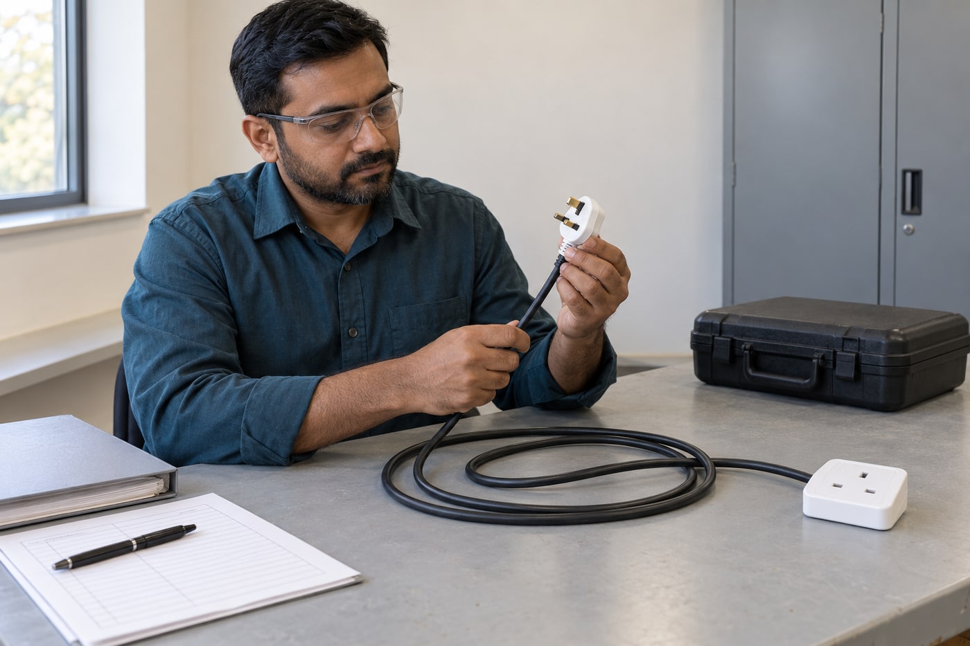
1. Confirm the lead and your competence
Use this procedure only if you are trained to inspect and test electrical equipment and can interpret the results. Identify a plain, passive, three-core BS 1363 extension lead with one socket and a protective-earth conductor. Establish its length, conductor cross-sectional area, rating and manufacturer instructions. Stop for unknown construction, surge protection, USB electronics, RCDs or cable reels. Use the PrimeTest 250+ manual and the applicable local inspection scheme; this tutorial does not establish permission to repair a lead or replace professional training.
Photorealistic illustration · Waey
2. Disconnect and control the complete lead
Unplug the extension from the building supply and remove every connected appliance or adaptor. Keep its supply plug visible and under your control throughout the assessment. Lay out the entire cable on a clean, dry bench without pulling it over sharp edges. Remove liquids and prevent another person reconnecting it. The cord test uses a closed connection to the battery-powered tester, not a wall socket. A non-contact voltage indicator is not evidence that the lead is safely disconnected.
Photorealistic illustration · Waey
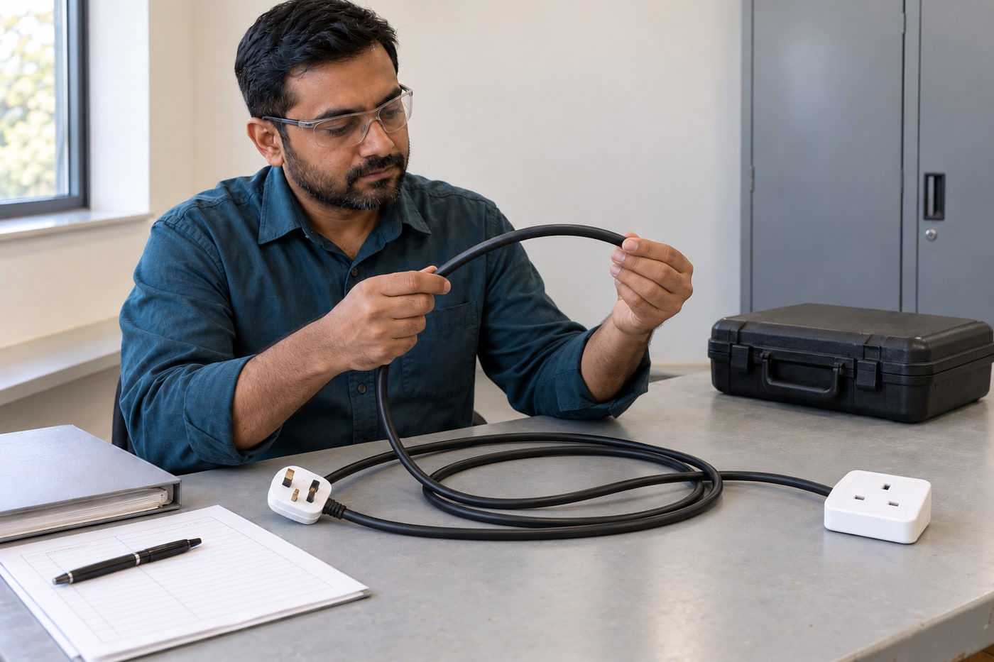
3. Inspect the whole assembly before testing
Examine the plug, pins, socket, shutters and the full cable length under good light. Look for heat damage, cracks, crushed sections, cuts, exposed insulation, loose parts or evidence of makeshift repairs. Check the rating and manufacturer identification remain legible. A visible safety defect means withdrawal from service even if an electrical test might pass. Record the location and nature of each defect. Do not tape over damage, straighten burnt pins or continue testing merely to obtain a pass label.
Photorealistic illustration · Waey
4. Complete the formal construction inspection
Follow the inspection requirements for the actual assembly. Where a rewireable plug is designed to be opened and your competence permits inspection, check the correct fuse, secure terminations, actual terminal markings and a cord grip retaining the outer sheath. Colour alone never establishes conductor function. Do not open sealed moulded components or improvise missing instructions. This procedure contains no rewiring or tightening recipe. Close any inspected enclosure correctly before testing; uncertain construction or a defect requires competent investigation and subsequent reassessment.

Photorealistic illustration · Waey
5. Prepare the tester and justified limits
Inspect the PrimeTest 250+ and supplied return lead for damage, dirt or moisture. Confirm verification status and follow the manual’s battery and pre-use checks. For this plain passive lead, check the normal 500 V insulation setting; the manual’s cord insulation threshold is 2 MΩ. Record the earth limit justified for the known cable and applicable scheme. Button 7 enters setup; CLII changes insulation voltage and CLI changes earth limit. Exit with button 7. Do not invent a lead-zeroing sequence absent from this manual.
Photorealistic illustration · Waey
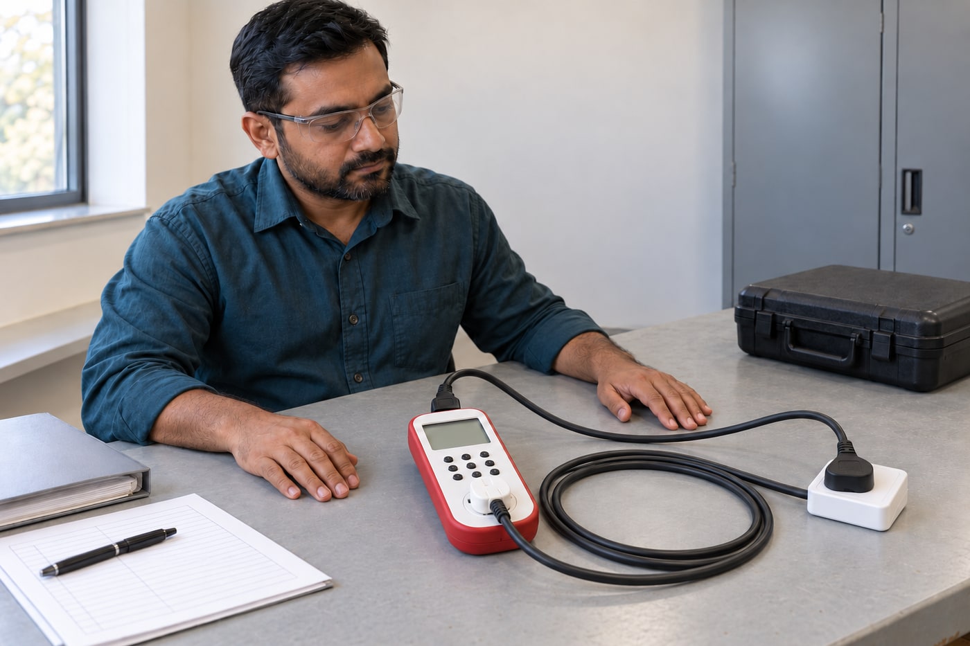
6. Connect the isolated cord-test loop
With no test running, insert the extension’s supply plug into the tester’s front test socket. Connect the supplied 0.5 m IEC return lead between the extension outlet and the tester’s IEC socket, following the PrimeTest 250+ cord-test diagram. Keep the extension disconnected from building mains and all appliances. Arrange the cable without tension and check each connection is fully seated. Do not substitute an improvised adaptor or connect an external supply to this loop. Resolve uncertain socket identification before proceeding.
Photorealistic illustration · Waey
7. Run the complete cord sequence safely
Keep everyone clear of conductive parts and press CLI to initiate the cord sequence described in the manual. The tester checks protective-earth continuity, insulation resistance and then wiring polarity. Although battery powered, it applies test voltage; do not touch contacts or change connections while a test is active. Watch for a stopped sequence or failure indication rather than assuming all stages ran. If the instrument reports an error, follow its manual and withdraw it when necessary; never open its case to investigate.
Photorealistic illustration · Waey
8. Interpret each result instead of overriding it
An earth or insulation failure stops the sequence and needs investigation. OPEN indicates an open live or neutral path, potentially including a blown fuse; Shor indicates a live-to-neutral short, and CrOS indicates reversed live and neutral. Record the displayed result accurately. A long-lead prompt is not permission to accept excessive resistance: interpretation requires known cable length, cross-section and applicable limits. If these are unavailable, stop. Never increase a limit or lower test voltage simply to convert an unexplained failure into a pass.

Photorealistic illustration · Waey
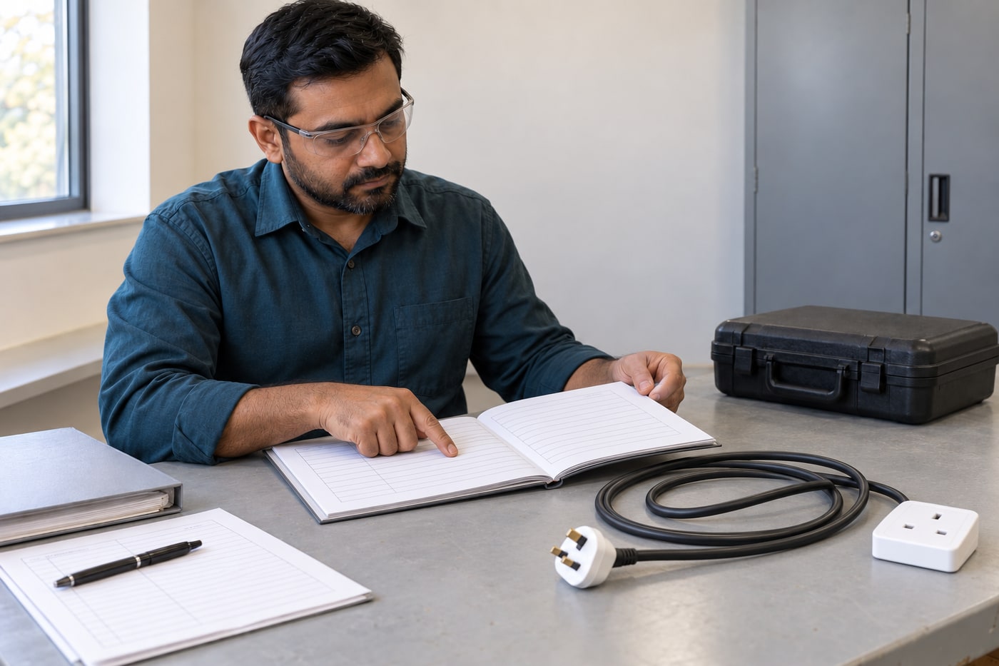
9. Record the assessment and its limitations
After testing has finished and the instrument is safe to disconnect under its manual, remove the connections. Record the lead identifier, construction, length and conductor size, visual findings, tester model and identifier, verification status, date, operator, selected settings, actual displayed measurements and each test outcome. Distinguish an incomplete sequence from a completed failure or pass. Record the basis for any long-lead interpretation. An illustrative photograph or a copied sample reading is not evidence that this particular lead has been tested.
Photorealistic illustration · Waey
10. Decide whether the lead can return to service
Return the lead to service only when the complete visual inspection and required electrical assessment are satisfactory under the applicable scheme. Identify and segregate failed or uncertain equipment so it cannot be reused accidentally; refer it for competent repair or replacement and the required reassessment. A pass does not permit overloading, daisy-chaining or unsafe routing. Follow the assembly’s rating and instructions during use. Set further inspection arrangements from its environment, use and risk assessment rather than inventing a universal annual test interval.
Video demonstrations
How to PAT test an extension lead - Seaward
Original manufacturer extension-lead demonstration with the exact PrimeTest 250+. Its public metadata and description were checked; no claim of full audiovisual review. Follow the matched written manual and justified limits.
Seaward Electronic Ltd. · en
Watch on YouTube ↗PAT Testing Extension Lead Test with the EZYPAT PLUS
Original manufacturer extension-lead demonstration using a Kewtech EZYPAT PLUS, a different instrument. Its buttons, connections and settings must not be copied to the PrimeTest 250+. Public metadata and description checked; no claim of full audiovisual review.
Kewtechcorp · en
Watch on YouTube ↗Final checks
Complete formal inspection and every required test, with actual recorded results and justified limits. Withdraw visible failures even when electrical readings appear satisfactory. UK workplace sources inform the method; applicable local rules and competent interpretation govern use.
Sources
PrimeTest 250+ Operating Instructions, 403A556 Revision 6 ↗
Seaward: interpreting long extension-lead resistance ↗
Six original AI-generated photographic illustrations across ten steps, with four stage-specific context reuses. Images illustrate inspection, disconnected setup and documentation; they contain no actual electrical readings or certification. No manufacturer photographs or diagrams were adapted. Original videos belong to their attributed creators.