
Build a plug-in LED task light beneath a desk shelf
Plan and build a neat low-voltage desk light: calculate the load, cut and connect compatible tape, fit a diffuser channel and manage glare and cables.
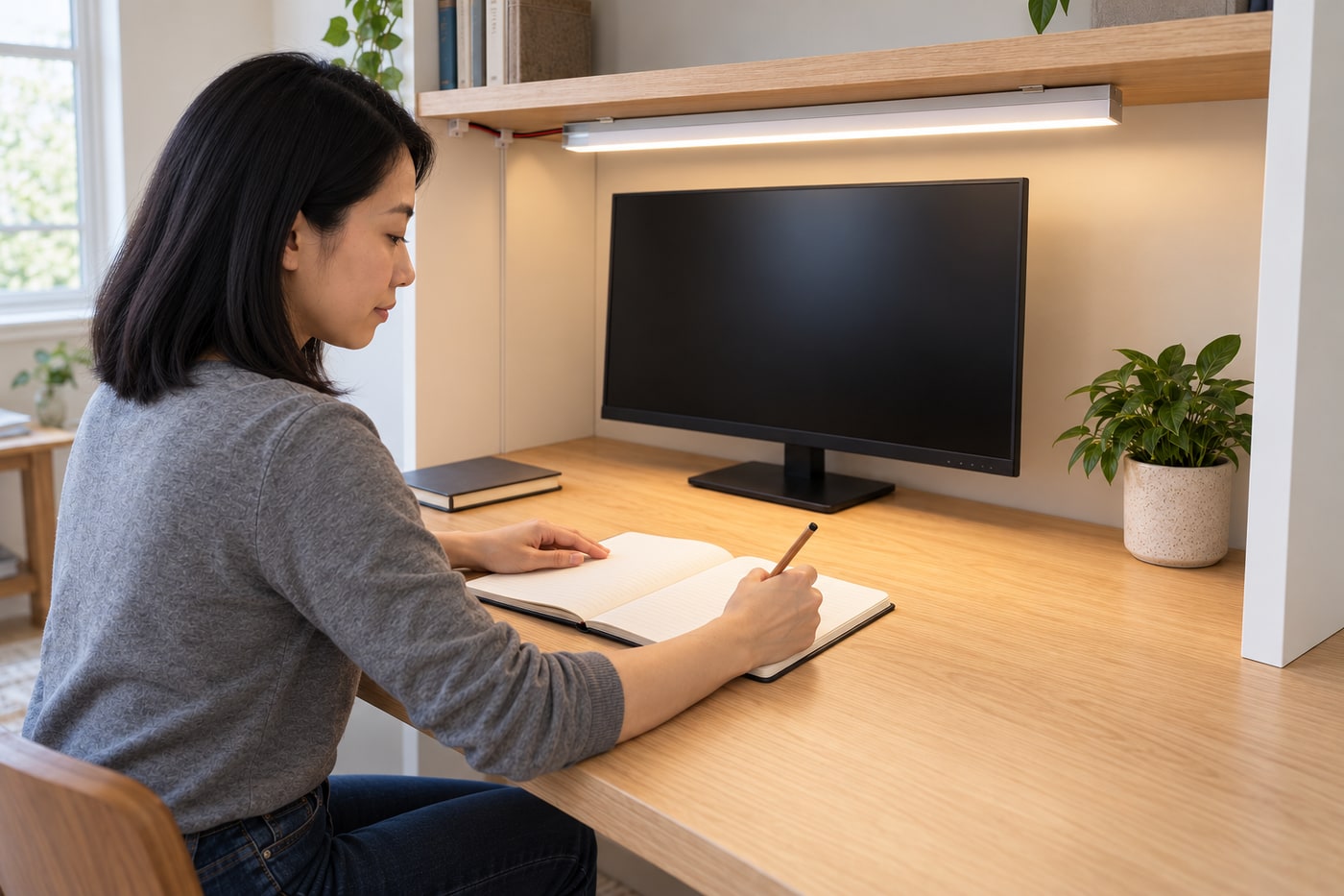
What will you learn?
Plan and build a neat low-voltage desk light: calculate the load, cut and connect compatible tape, fit a diffuser channel and manage glare and cables.
Tools
- Tape measure; pencil; straightedgeSearch Amazon Saudi Arabia ↗
- Sharp scissors suitable for the tape; matching hand screwdriverSearch Amazon Saudi Arabia ↗
- Drill, specified pilot bit and reliable depth stop only if the clip instructions require pilot holes; eye protectionSearch Amazon Saudi Arabia ↗
- Clean lint-free cloth and manufacturer-approved surface-cleaning materialsSearch Amazon Saudi Arabia ↗
Materials
- One compatible 24V DC white LED strip, two-contact connector and ready-made leadSearch Amazon Saudi Arabia ↗
- Factory-enclosed locally approved plug-in constant-voltage 24V supply and compatible low-voltage dimmer, rated for the calculated loadSearch Amazon Saudi Arabia ↗
- Aluminium channel supplied to the required length, matching diffuser/end caps/clips and suitable short fixing screwsSearch Amazon Saudi Arabia ↗
- Suitable surface cable clips or trunking; stable existing solid-wood desk-hutch shelfSearch Amazon Saudi Arabia ↗
Step by step
Photorealistic illustration · Waey
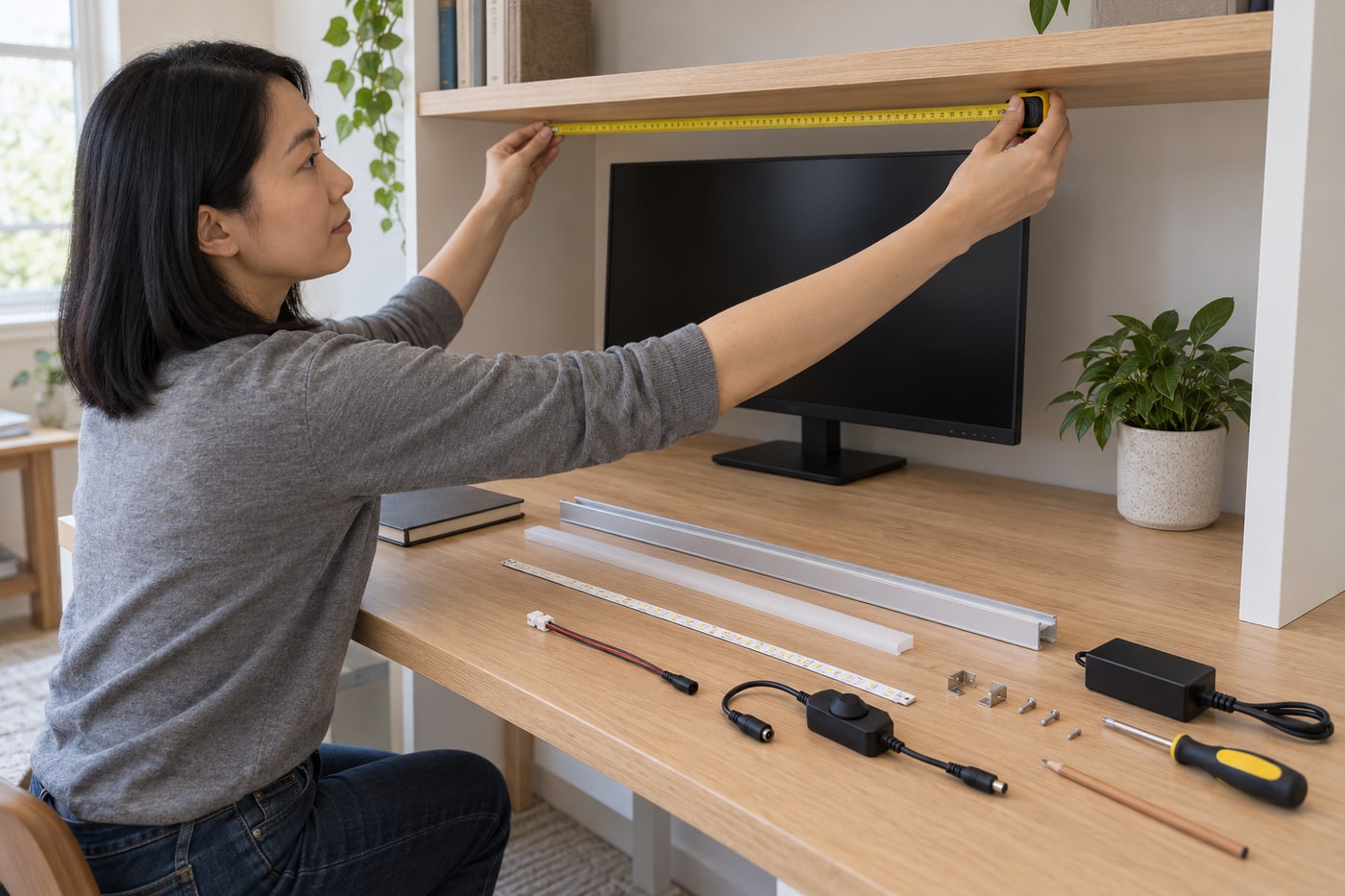
1. Plan the light and cable route at the desk
Use a stable existing desk hutch with a sound solid shelf, leaving its structure and wall fixings unchanged. Measure the usable underside and allow space for the channel’s end caps, connector and cable exit. Position the light so it reaches the writing area while the shelf edge shields the LEDs from your seated eyes and monitor. Plan an accessible, ventilated place for the closed power adapter and dimmer, plus a protected surface cable route that will not cross drawers, chair movement or hot equipment.
Photorealistic illustration · Waey
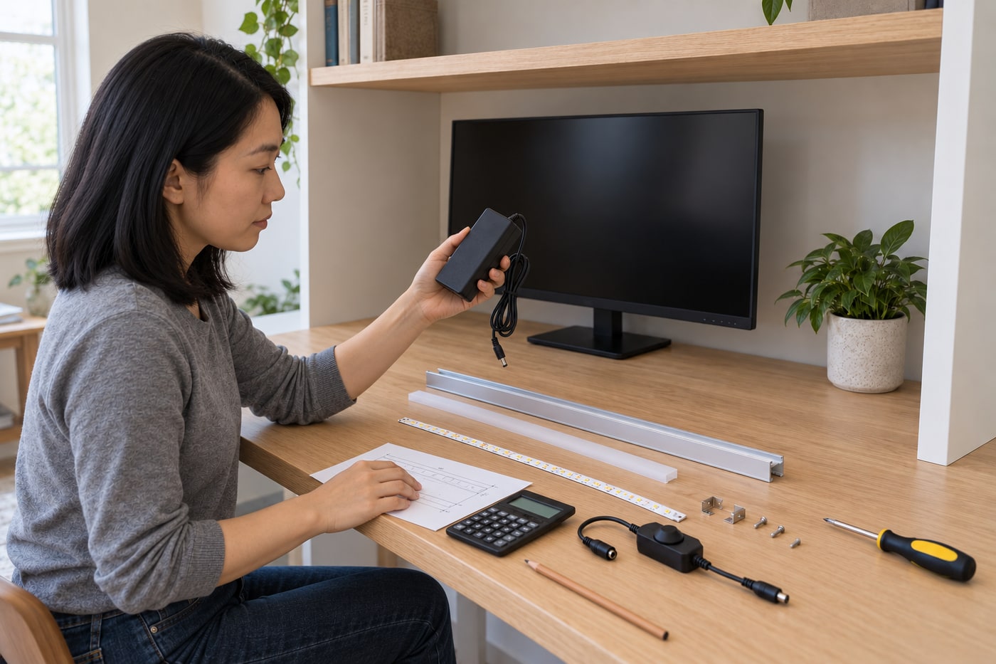
2. Match the strip, controller and plug-in supply
Choose one compatible constant-voltage system: the illustrated project uses 24V DC white LED tape, a matching low-voltage dimmer and a factory-enclosed plug-in supply approved for your local mains voltage and plug. Read all actual ratings. For a hypothetical one-metre strip rated 9.6W per metre, the strip load is 9.6W and its nominal current is 9.6÷24=0.4A. Use the maker’s actual load table, controller limits and supply derating/headroom instructions. Extra wattage does not make the wrong voltage, polarity or connector safe.
Photorealistic illustration · Waey
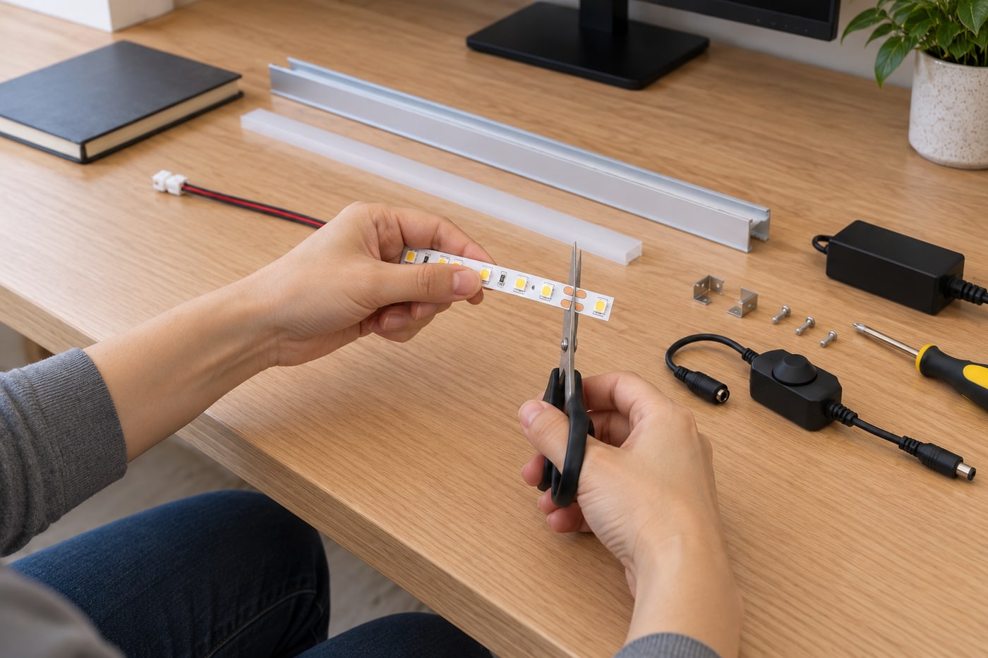
3. Disconnect everything and cut only at an approved mark
Keep the adapter unplugged from the wall before cutting, connecting or mounting. Lay the tape straight on a clean non-conductive surface, allowing for the connector and end caps before choosing the last permitted cut point. With sharp scissors, cut squarely across the centre of the marked copper pads only where the tape manufacturer permits a solderless connector. Do not cut through an LED or resistor, use a soldered joint as a connector pad, or shorten any mains cable. Obtain a suitably sized channel rather than improvising a metal-cutting setup at the desk.
Photorealistic illustration · Waey
4. Fit the correct two-contact connector
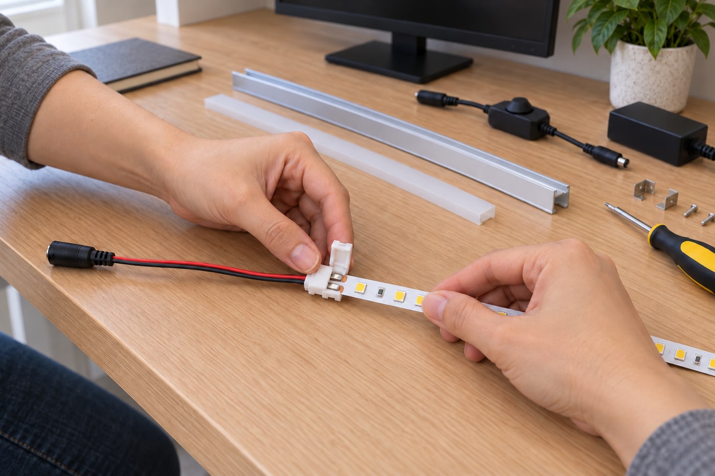
Use a connector specified for this tape’s width, contact count and electrical load; a two-contact white strip differs from RGB and tunable-white systems. Open the latch and expose only the backing section required by its instructions, leaving the adhesive in place. Slide the tape fully into the guides so clean copper pads meet the contacts, matching the actual plus and minus markings to the lead and controller. Close the latch as directed and check seating without pulling on delicate pads. Never rely solely on wire colour or force an incompatible clip.
Photorealistic illustration · Waey
5. Test the complete low-voltage assembly before fixing it
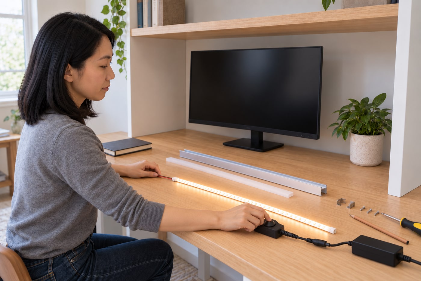
With power still disconnected, join the finished strip lead, compatible dimmer and supply through their specified ready-made connectors. Lay the full strip out straight and supported, clear of metal tools; never power it tightly coiled. Inspect for loose contacts, exposed conductors and polarity errors, then plug in the closed adapter for a brief functional test using the normal control. Check every section and dimming operation. If anything flickers or fails, unplug before investigating the low-voltage connections. Unplug again before proceeding with installation.
Photorealistic illustration · Waey
6. Install the channel clips without penetrating the shelf
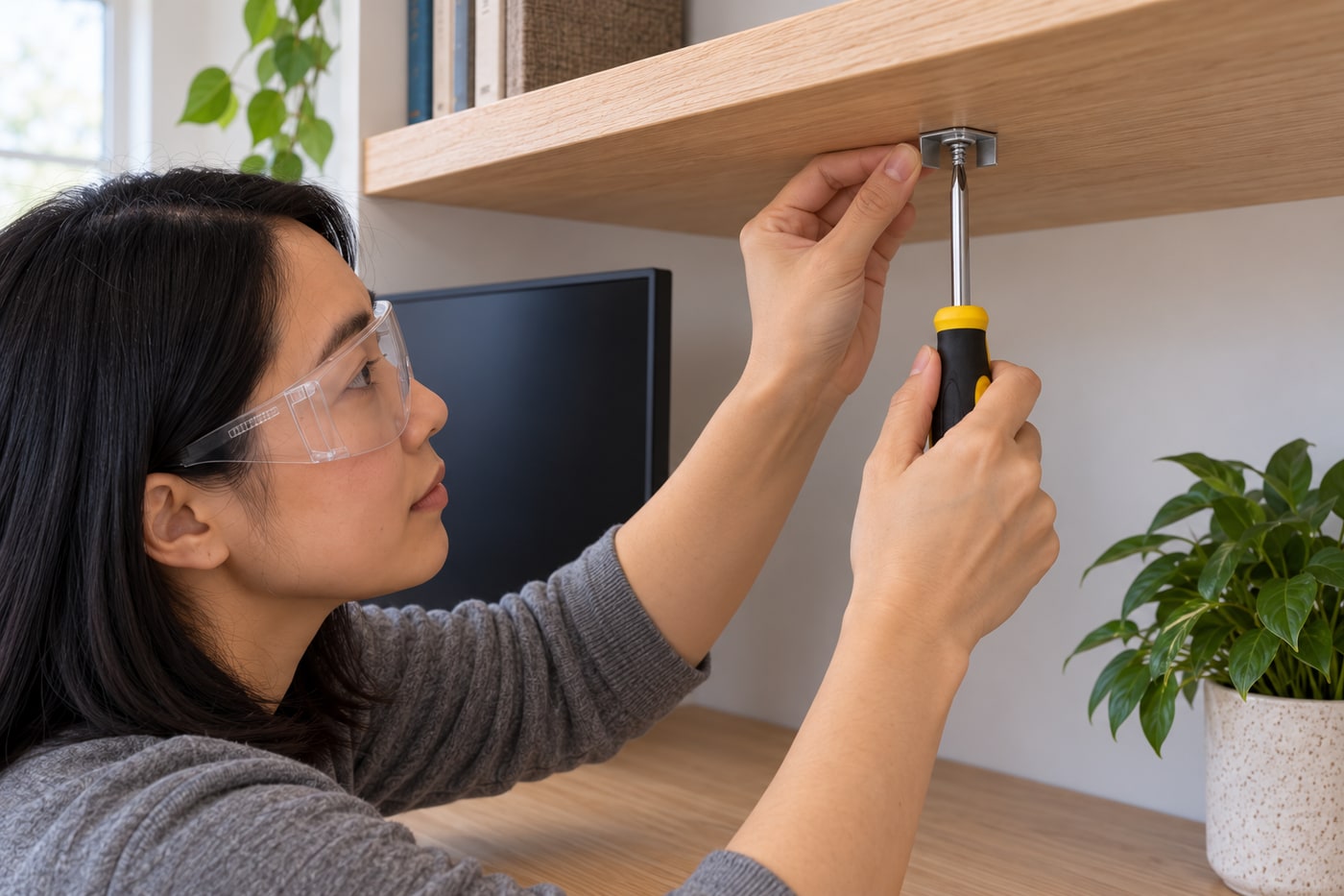
Mark the clip positions from the channel instructions on the underside of the known solid shelf. Confirm its thickness, the clip thickness, screw penetration and any required pilot-hole depth before using a tool; do not assume the supplied screws suit every panel. Where specified, use an appropriately sized pilot bit with a reliable depth stop, eye protection and a stable working position. Keep cables and electrical parts away from drilling. Secure the clips with a hand screwdriver, stopping snug without stripping the wood. Do not drill into walls, hollow panels, hidden wiring or the adapter.
Photorealistic illustration · Waey
7. Attach the tape inside the clean aluminium profile
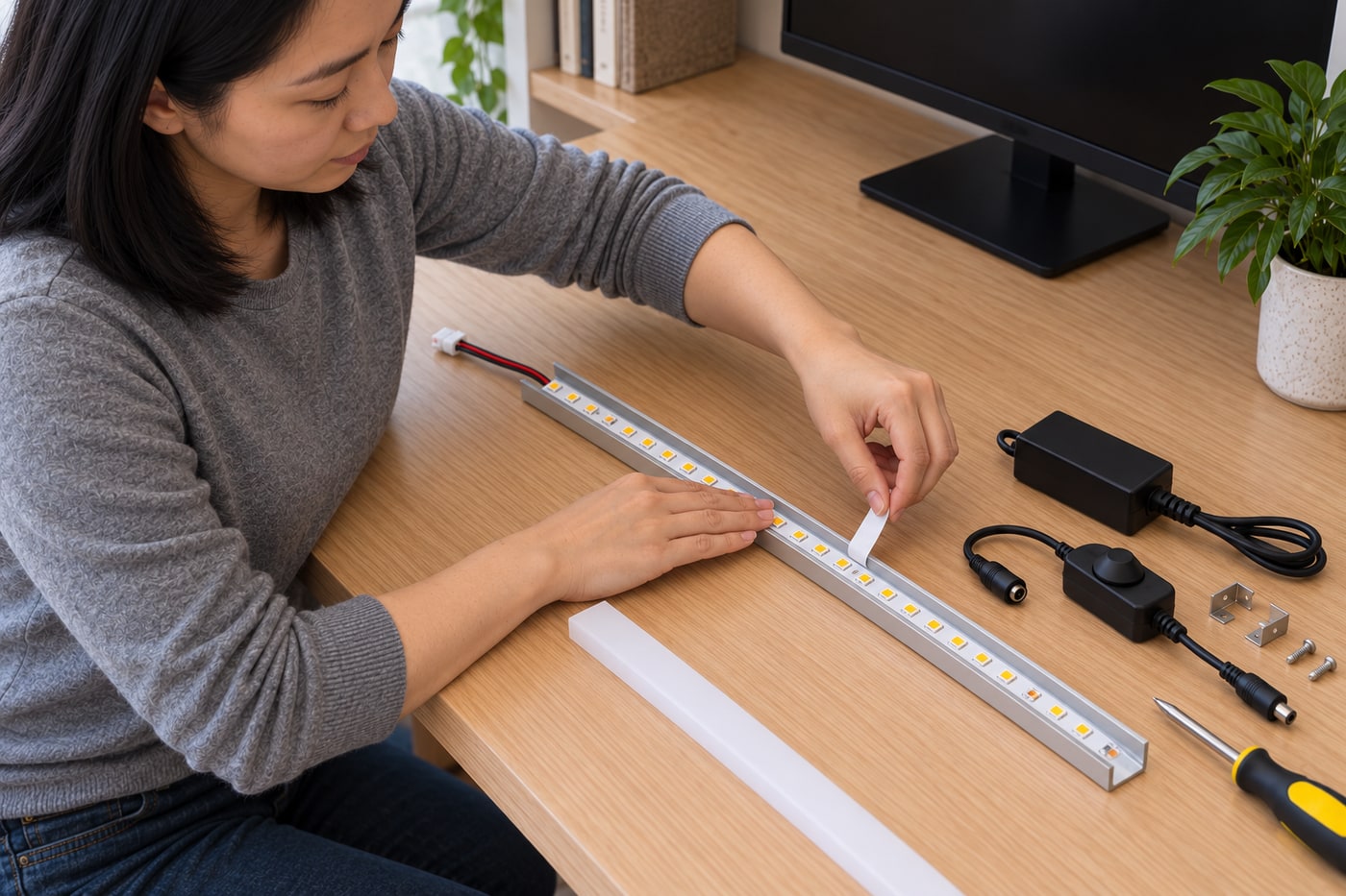
Clean and dry the channel using the surface-preparation method approved for its finish and the tape adhesive. With power disconnected, lay the strip in place to check that its connector fits and the cable exits without a sharp bend. Peel the backing a short section at a time and press the tape gently onto the channel base without crushing LEDs or scraping components against an edge. Keep the strip flat and within its allowed bend limits. Follow any adhesive settling time; do not repeatedly peel and restick a permanent backing.
Photorealistic illustration · Waey
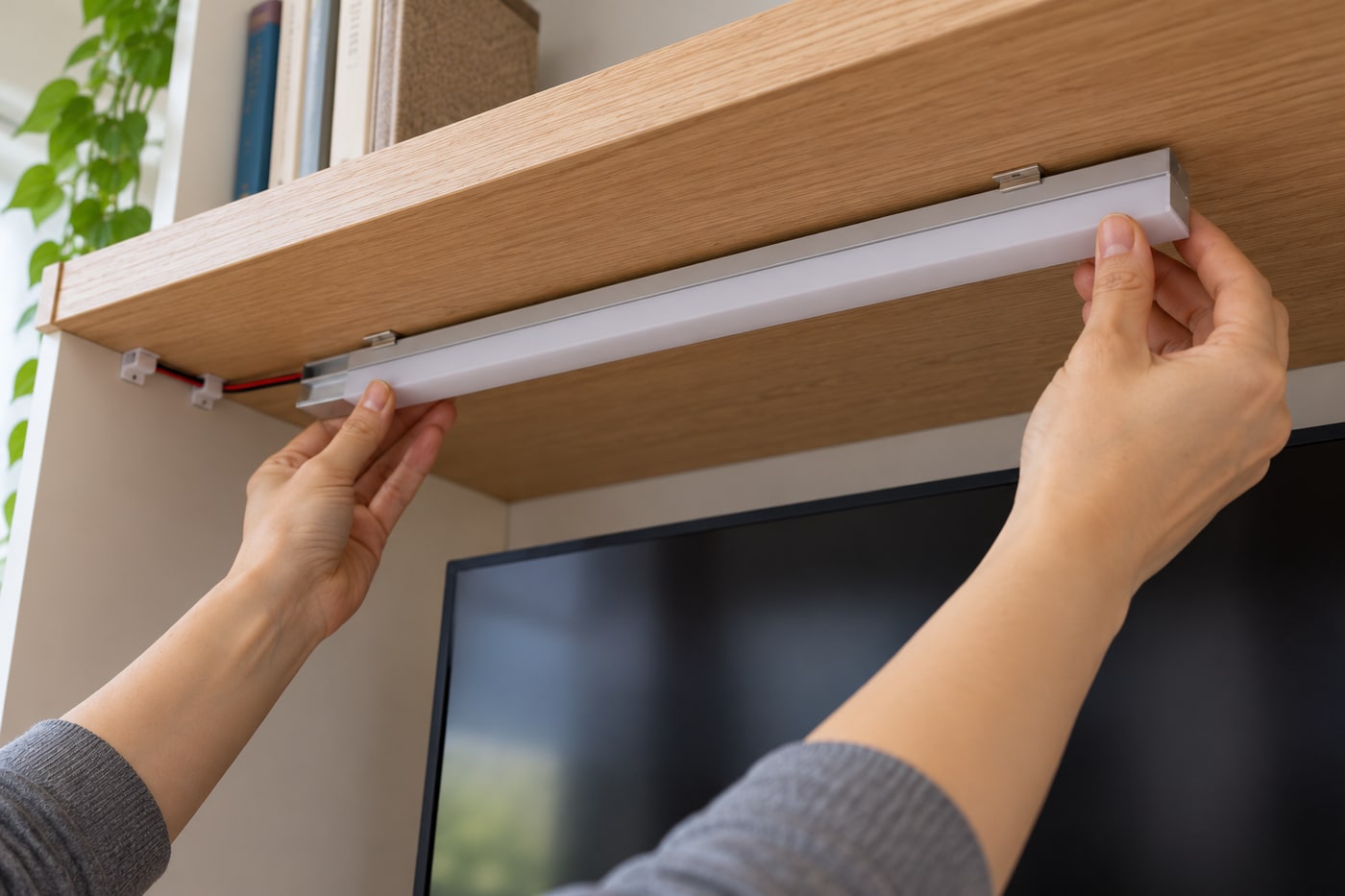
8. Fit the diffuser and secure the cable run
Fit the correct end caps and milky diffuser as the channel instructions show, keeping the cable clear of pinching points and leaving all required ventilation unobstructed. Clip the completed profile into its mounts and support the lead with suitable cable clips or surface trunking, without staples through insulation or tight cable ties. Keep the adapter accessible and uncovered in its intended ventilated position, with slack for normal desk use. This project uses surface low-voltage connections only: do not conceal joints inside walls or modify mains wiring to hide the supply.
Photorealistic illustration · Waey
9. Test from the seated position and inspect normal operation
Reconnect only after the strip, connectors, diffuser and cable route are secure and tools are removed. Test brightness and dimming while seated, checking the page and screen together for shadows, visible LED glare or reflections. Adjust the supported light position or brightness rather than covering the adapter or LEDs with cloth. Follow the equipment’s normal-operation checks; disconnect for unusual heat, smell, flickering or loose connections instead of opening the adapter. Record component ratings and the cable route so later furniture changes do not trap or overload the installation.
Video demonstrations
LED Strip Light Kit - How To Troubleshoot Polarity Issues
Manufacturer explains polarity mismatches in strip-light kits. Disconnect before changing connections; this guide uses a white two-contact strip and ready-made low-voltage leads.
Armacost Lighting · English
Watch on YouTube ↗How to choosing the Proper LED Driver / Power Supply for an LED Lighting System
Explains selecting a driver and control method. Some examples use US120V mains or hardwired drivers: this project uses only a locally approved closed plug-in supply, with no mains-terminal work.
Armacost Lighting · English
Watch on YouTube ↗How to use LED Strip Light wire-to-tape light connectors
Shows strip connector types and their application. Match the actual tape width, contact count and connector instructions; the illustrated two-contact white strip is not RGB or tunable white.
Armacost Lighting · English
Watch on YouTube ↗Final checks
All components voltage/polarity/load compatible; connectors secured; channel and cables supported; supply ventilated and accessible; light comfortable at the desk with no abnormal operation.
Sources
Armacost: strip preparation, cutting, polarity, mounting and power limits ↗
Armacost: model-specific wattage tables ↗
Flexfire: surface-mount channel installation ↗
Super Bright LEDs: channel, diffuser and end-cap fitting ↗
IKEA: separate supply sizing, component compatibility and practical placement ↗
Armacost: original instructional videos for driver selection, polarity and strip connectors ↗
Photographs are credited beside each image. Generated photorealistic illustrations by Waey; linked videos remain with their creators.